What is AC Coupling.
‘OzInverter’ AC COUPLING, and Back
charging the batteries.
For true total domestic renewable independents,
or as it is referred to OFF GRID or MINI GRID.
I have always seen AC coupling
as the way forward, rather than just DC and many expensive charge controllers
just feeding the batteries and powering a large Inverter that creates 240vac 50HZ PSW, (pure sign wave), or 120vac at 60HZ PSW.
Some time ago I originally bought a very
expensive, so called Rolls Royce of commercial Inverters, 48vdc to 240vac, firstly
it couldn't do the specified 6kW and found that it could only do 4.2kW
constantly. Secondly it needed a lot of expensive propriety ancillary control
equipment to function and back charge the batteries correctly. And thirdly It
raised the 240vac HZ frequency from 50HZ to 60HZ and domestic equipment failed.
It went back, and the company put a gagging
order on me not to talk about their crap toy Inverter.
'Oztules', on Flinders Island, Tasmania, stepped
in, and like me he wanted a true and real Inverter that would do the AC
coupling using a H bridge design, and without all the fuss. Our Mantra
.... KEEP IT SIMPLE, MAKE IT ROBUST, and importantly MAKE IT COST EFFECTIVE.
And hence we designed and created the efficient and powerfull ‘OzInverter’, that you can make your self for about 800 euros. And yes, I can supply all the necessary PCB boards and a DIY Book. See …………. Leslie Bryan Microengineering (bryanhorology.com)
A very cost-effective solution for handling that
19kW of power from the PV panels arrays, is to use what is called 'AC
Coupling'.
Houses that you see around the World with PV on
the roofs will be using standard manufactured GTI's, (Grid Tied Inverters) that take the PV DC output
and change it to AC and feed it back at a few volts more into the Mains
Utilities Grid for that Country.
These GTI's are slave machines
and need to see the correct AC voltage and the correct HZ frequency, so to get their
internal electronics/transformer to operate before they will feed into the Grid
a few volts over the Mains Utilities supplied voltage.
There are many Good Quality GTI's available
second hand, i use fleebay etc, and i prefer GTI's with a toroid transformer,
see below photo of previously used SMA's........ . 150
to 300 Euros each.
Now our 48vdc ‘OzInverter’ creates a very stable
240vac or 120vac at a stable 50H or 60HZ, depends on your country domestic
voltage, and therefore allows 'AC Coupling'.
The GTI's back charge through the ‘OzInverter’ to the battery bank any
surplus power not being used on the OFF GRID or we call our ‘OzInverter’
created MINI GRID.
Three methods of controlling the back
charging from GTI's is possible for 'AC Coupling'.
A.
Use the Internal codes/settings in the GTI's to sequential shut down
when a specified ac output voltage is reached. This works reasonably well with
my system as some installations GTI,s are up to 400 meters away from the ‘OzInverter’
and batteries, and the batteries do push back slightly, but this depends on the
cable voltage sag.
B.
Use dc voltage comparators circuit to shut down the GTI ac side with a
relay when the DC battery voltage rises above a charging rate voltage. But you
will need to run a data cable to all your installations, and again allow for
voltage sag.
C.
Use PWM dc controllers that are connected directly to the 48vdc
battery bank. These Diversion controllers, (Morningstar Tristar PWM at about
200 Euros each), will regulate the charging and any excess power when the
batteries are full and will dump/divert to other permanently connected sources,
ie, Air Heaters 2kW each or Hot water heaters, underfloor electric heating, etc.
The above are a cost effective and very reliable
system.
A is used most, and C is my guaranteed
safety system. Where i do not have access to the GTI internals, then i use B.
For a 19kW Array I prefer using 2off 1.7kW &
4off 2.5kW GTI's for 14kW, and using DC Charge controllers for the 5kW as these
can gently finish charging that precious 48vdc battery bank.
NOTE, I have not used a HF, High
Frequency GTI, because second hand old heavy toroidal types are easily
obtainable and very cheap, plus you get to use the GTI internal MPPT .
'Oztules' and others have experimented with HF types and do not find any real
difficulties.
NOTE. Its best to use GTI’s at a max output of 2.5kW as above this the GTI tends to surge on a long cable connection.
I trust this information helps.
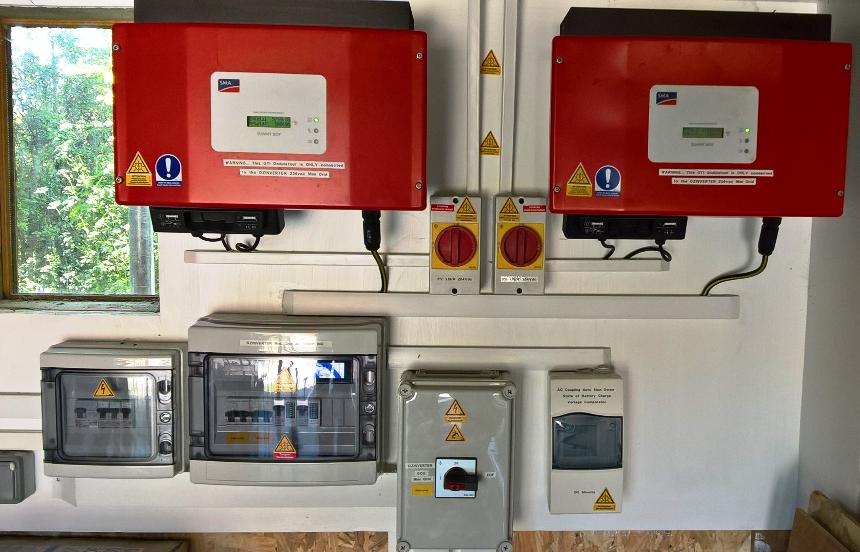
The two red boxes in the above photo are standard GTI's that are used/second hand.
Each is rated at 1.8kW and capable of converting the ever fluctuating sun shining PV DC voltage to 240vAC to feed into our MINI GRID. This Garage roof PV install has 3.6kW max of PV and i have spilt them into 2 PV strings of 1.8kW each so just about correct for each GTI.
With the 8010 microprocessor Its the soft start that with large toroid's needs to happen, because a toroid can pull huge surges, you will see this with the OzInverter when testing procedures on just the toroid when you are winding it. Its in the book.
For USA use, 120vac 60HZ, you just add in a centre tap when you are winding the secondary on the bare toroid, so 130 turns then take a tap at 65 turns, this means that all the control board components and the way it works stays the same, but with the taps you get 120vac on each side of the tap and 240 on the main secondary winding of say 130 turns. This then does not interfere with the Voltage and amperage controls on the Control board. However i have also produced a 60HZ control board, and this has a slight modification to the tracks to get the 8010 chip to output at 60HZ.
I explain and show lots of photos etc, in the book.
Sometimes its best if you have a reasonable mechanical engineering skills as this is real POWER electronics/electrics, and some just electronic guys find it a challenging doing the chunky stuff.
The 3 PCB's are all through hole components and all readily obtainable, and the only SMD 8010 processor is fitted on a daughter board. The PCB tracks are wide and large and the solder points are reasonable large to avoid PCB substrate separation. The PCB's were deliberately designed to be easily repaired and components replaced without difficulties, ie we kept it simple and robust.
Anyways i point out the critical bits. To Achieve AC Coupling with the Bi Derctional Oz Inverter, you don't need add any more ancillary equipment or change or write any code, as we use the 8010 SMD chip which according to 'FRACKERS' has about 64k of code already written in it.
With the 8010 microprocessor Its the soft start that with large toroid's needs to happen, because a toroid can pull huge surges, you will see this with the OzInverter when testing procedures on just the toroid when you are winding it. Its in the book.
For USA use, 120vac 60HZ, you just add in a centre tap when you are winding the secondary on the bare toroid, so 130 turns then take a tap at 65 turns, this means that all the control board components and the way it works stays the same, but with the taps you get 120vac on each side of the tap and 240 on the main secondary winding of say 130 turns. This then does not interfere with the Voltage and amperage controls on the Control board. However i have also produced a 60HZ control board, and this has a slight modification to the tracks to get the 8010 chip to output at 60HZ.
I explain and show lots of photos etc, in the book.
Sometimes its best if you have a reasonable mechanical engineering skills as this is real POWER electronics/electrics, and some just electronic guys find it a challenging doing the chunky stuff.
The 3 PCB's are all through hole components and all readily obtainable, and the only SMD 8010 processor is fitted on a daughter board. The PCB tracks are wide and large and the solder points are reasonable large to avoid PCB substrate separation. The PCB's were deliberately designed to be easily repaired and components replaced with out difficulties, ie we kept it simple and robust.
Anyways i point out the critical bits.