How to make your own real 6kW, 240vac or 120vac, pure sine wave OzInverter that is powered by 48vdc.
The OzInverter.
Brief notes on its substance and its development.
Firstly, Why the name OzInverter?....
It is named after the Renewable Forums member name ‘Oztules,’ Flinders Island, Tasmania, Australia, who in 2015, helped me achieve a simple, robust, powerfull and cost effective Inverter. His work is ‘Open source' with his experiments and actual builds, are detailed in the below mentioned World Wide Renewable Energy Forums:-
http://www.anotherpower.com
http://www.fieldlines.com
http://www.thebackshed.com
For decades I had been searching for a simple, robust 48vdc (batteries) to 230vac 50HZ Pure Sine Wave Inverter that will actually do and deliver the kW’s it says it can, and also hold a stable HZ frequency. Oztules helped me to achieve my dream Inverter, and it runs beautifully.
Most folk with normal homes that are Off Grid or want to be, need about 3 to 5kW of power around the house. Sometimes they may need 6kW for ½ hour or so, or infrequently up to 15kW , the OzInverter will do this, that’s if your batteries can take/handle it.
AC Coupling, Mini Grid.
With the arrival of GTI’s, (Grid Tie Inverters) that uses the PV on the roof of houses, and subsequent lowering of prices, and the availability of second hand or old stock, we can now directly feed the AC output from the GTI’s into our OzInverter created mini AC grid. So we no longer need as many costly DC battery chargers/controllers.
If you are not using the GTI’s output around the home, then the Excess 230vac AC will backfeed through the OzInverter and become DC and charge your batteries, which is what I do. Some sort of battery charging regime will be required.
As your batteries fill and become full, the OzInverter raises the 230vac voltage slightly, and with most normal GTI’s this then goes outside their normal working parameters, and hence the GTI shuts down. In the book, I also talk about a fail safe protection for the batteries.
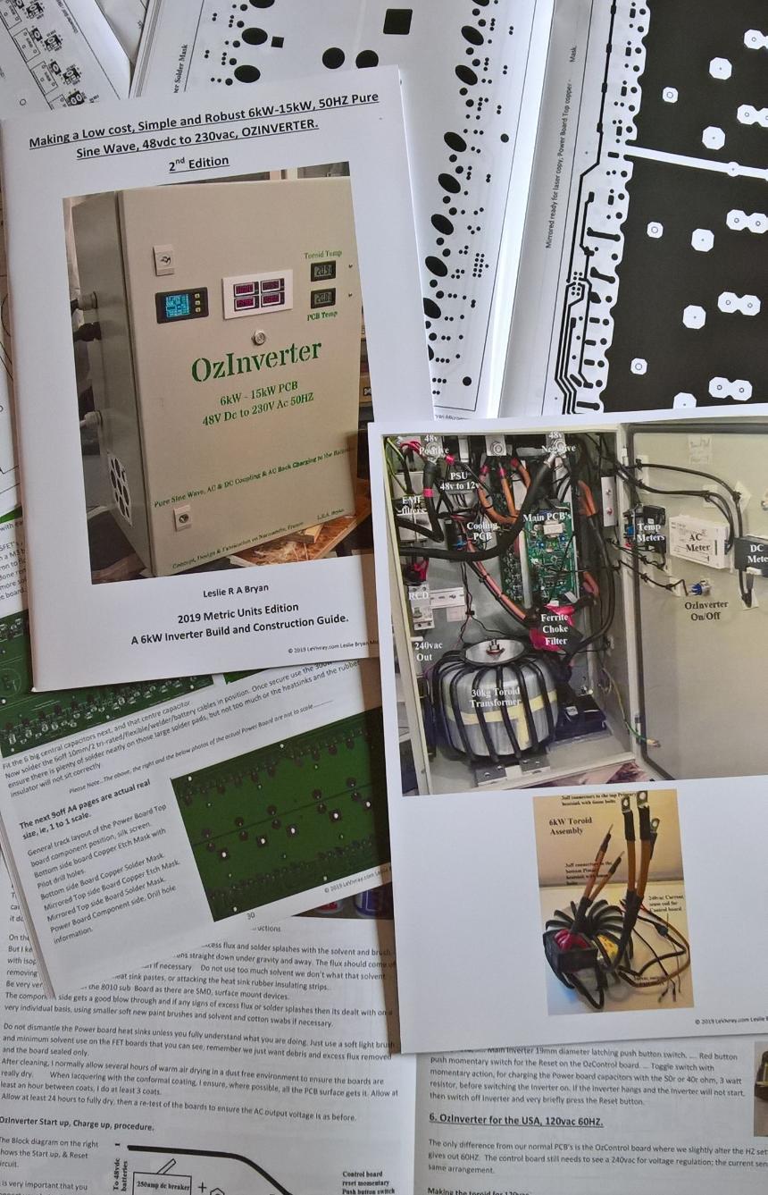
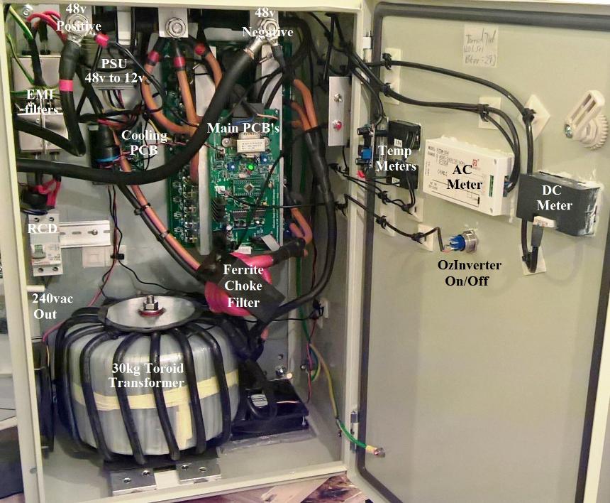
The Photo of the inside, shows our own PCB boards, with our double copper thickness Power board, Control board and cooling board. The second edition OzInverter book shows all the necessary Photo etch masks/screens for all three boards.
What can the OzInverter do?.
The Toroid transformer is the key here, for a 6kW Inverter we are talking about 26kg to 30kg of laminated wound silicone iron core, with a centre hole say about 100mm diameter. This will then match with our Power Board and its matching Control board.
No commercial available toroid will do, we stack cores, do the maths on the cross section mm/2, (real working figures), gives us a rough guide on the Secondary windings and Primary windings from the known ratio. (Its in the book).
We wind the large toroid by hand, (photo example of the table set up is in the Book), as no commercial winding machine can get into our stacked cores. We mylar tape and epoxy each winding, this stops the buzzing and movement of the windings so eliminating early failure due to internal vibration and the consequent shorting out.
We test each winding for correct turns etc, we wind a low count single primary core, about 50mm/2, better cooling abilities, we bench test it and test the secondary and amend the primary turn to get what we want.
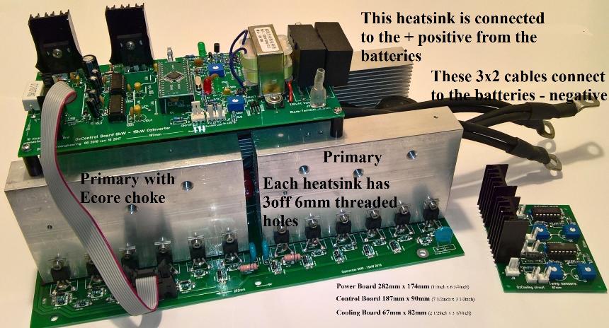
Importantly, the Power Board and the Control board have been designed for through hole components and that are readily available, and designed for ease of self-manufacture. They will take 6kW and up to 15kw but cooling is the key here, again its in the book with the OzCooling circuit and Board.
If you follow the book’s methods, you end up with a robust, simple, stonking big, serious Power Inverter, and all at a very reasonable Price.
There is now a Chapter and addendum for our American cousins that require a 60HZ and a 120vac supply.
The New 2nd Edition. Making a Low cost, simple and robust 6kW, 50HZ Pure Sine Wave, 48vdc to 230vac, INVERTER.
Those that have followed ‘Oztules’, wonderful endeavours will understand that for posterity and easy reference, and for my boys, I have put together a Book that gives the technical, describes and shows (lots of colour photos), the OzInverters I built and now run.
There is no money in this book publication, we are not a commercial organization, we just want our costs and P+P, but it’s good to finally see all that Information is in one place, in a Book.
June 2019, the Control board still uses the 8010 chip, these SMD PWM chips are still readily avavailble. In the 2nd Edition book I now also show some new and interesting Inverter concepts that are being developed where the PWM is achieved with NANO chips with there specially written code..
Extra time was taken on the design and construction of the PCB’s, so to ensure robustness and that all components and parts of the New OzInverter were easily obtainable.
“Looking good.. now with just off the shelf components, we can finally make a real inverter.. that is easy to fix as well. utopia indeed for remote living I don't think any other unit on the market can say that.... usually you have to replace propriety boards... if you can get them. . ‘oztules.’
The first edtition covered the PowerJack Chinese made boards Book. ISBN 9780993590306. A4 Size, 76 printed pages, 151 colour photographs, 14 diagrams.
The NEW SECOND EDTION, ISBN 978-0-9935903-2-0 2nd edition has 92 pages with 34,000 words and 221 colour photographs and 12 diagrams, its a WORKSHOP/construction MANUAL.
What’s in the 2nd edition Book ?
Absolutely Everything, explaining & showing and very explicit …. From the Core, winding the toroid, to the PCB’s, build techniques and advive, and all the other necessary components to give you a Real Working 6kW OzInverter.
Update Wednesday 20 Dec 2023.
As these PCB boards are A4 size, large and use the thicker 2oz copper and are also expensive for me to provide, and its difficult to find a European supplier.
For those of you that have my Power boards already and therefore my real email address, i can send you the XGerber files for the Power Board PCB and you can have your own made.
If you purchase the book through Paypal i will send to your email the X Gerber files so you can manufacture your own.
ISBN 978-09935903-2-0
OPTION 1.
2nd Edition, A 6kW OzInverter Build & Construction Guide.
£32 GBP.
Includes postage and tracking to most places in the World.
Please see below exceptions where international tracking does not function
The OzInverter Book, and the OzInverter Book and the 3PCB's option, normal Post office tracking function does not always function in certain countries.
Example, ... I am willing to send to Brazil but a book can take up to 16 weeks to reach its destination and I cannot guarantee the book is in the postal system as the international tracking numbering does not always function.
Paypal require me to have tracking numbers to prove I have sent the item, however if the tracking number does not work, then Paypal are quick to refund the original buyer/purchaser and I loose.
As I have already said, “we are not a ‘charity’ and we are not a ‘commercial concern’ with this book & PCB’s, we just want to help others “.
November 2021. …….. Please Note, Do not start drilling the HEAT SINKS on the Power Board until you have the PCB, use the PCB to mark out the position of your holes for drilling/tapping on your heat sink, and the FET mounting holes..
Please Note, When drilling the heatsinks for the holding bolts/screws, please be aware that a slight de-scaling by the printers has taken place. And when using the Power Board DRILL HOLE MASK, on page 37, the power board PCB that we produce and send out is correct size, but the mask is 3mm shorter and 1.5mm in width compared to the PCB.
So please ensure you use the POWER BOARD that we produce, or you produce, as the DRILL HOLE MASK, especially for the Heat Sinks. If you have already drilled the heat sinks and the holding holes are in the wrong place compared to the PCB, then the heat sink can be turned over. DO NOT MAKE THE PCB HOLES ANY BIGGER.
Amendments 2019.
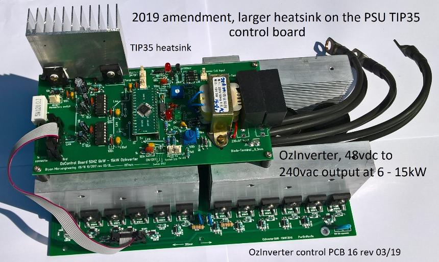
OzControl board 16 rev 3/19, and onward, has the 2 TIP35 realigned so a larger heatsink can be fitted.
These 2 TIP35's are the voltage supply for the 15v for the 2 FET drivers 2110, and the 5v + - for the 8010 SMD main chip. They get warm when operating so a good heatsink is important ..... see photo below.
COOLING A MAIN POWER INVERTER .
My personal experience and observations after 14 years of making, installs and running Inverters, and having that vital Empirical Evidence.
I have put this together for others, this all may seem ‘common sense’, but to get that ‘common sense’ you need actual hands on experience information.
1 …….. Your main 48v DC to 230v AC (or 120vac in the US) should be kept cool at all times.
2…….. Firstly, DO NOT INSTALL the Inverter in the same room or compartment as the batteries.
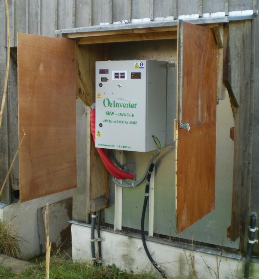
3. ....... Your Inverter should have good access to air flow. But keep the weather elements away from the actual machine.
Excess heat in your inverter when under load, will lead to rapid wear down on the electronic components, notably the Capacitors and the toroid windings.
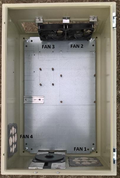
Ensure that the enclosure for the Inverter allows good air flow, for the PCB’s and the toroid. And for the 6kW OzInverter I recommend the double ozcooling circuit that’s temp and delay adjustable, for sucking in with a 120mm diameter fan at the bottom blowing air direct onto the toroid and another sucking the air out at the top of the enclosure. And 2 more 120 mm diameter fans with the PCB boards that are fastened vertically.
Use stainless steel insect mesh to stop spiders etc from getting into the Inverter machine. As Oztules found out, “The local moths liked my LED’s on the control board and snuggled up to it until the Control board shorted out.” Keep the insect mesh clear, its surprising that insects and debris soon clog the mesh.
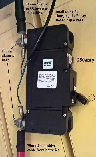
Batteries, especially Lead Acid need to be in their own separate environment, with lots of air flow to disperse the Hydrogen that is given off. The Inverter and the Inverter main fuse should be in their own separate environment.
I have seen Blue gently glowing balls of methane and hydrogen slowly ascending from our battery shed on a still foggy autumn evening, they dissipate at about 10 meters high after 10 to 15 seconds. I have also seen that when a main 250amp breaker has been engaged in the battery room, for just a split second all the spider cobwebs glowed, so not a good idea to have electrical connections in the battery room.
For a permanent 24/7 inverter installation, a good solution is to have the Inverter the other side of the wall to the battery room, this keeps the 70mm/2 cable reasonably short, so voltage sag is minimal. And have the Inverter in a good weather/rain proof cabinet that keeps it dry and protected from beast and small animals, but importantly allows lots of air to flow around it.
Ensure your cables are encased in cable protection from ‘furry critters’.
Now some of you may say, “I will have the inverter inside my house”, well firstly the constant very gentle Hum from the hand made toroid and the Choke assembly are always there, and with commercial manufactured inverters they can sound like a bag of spanners.