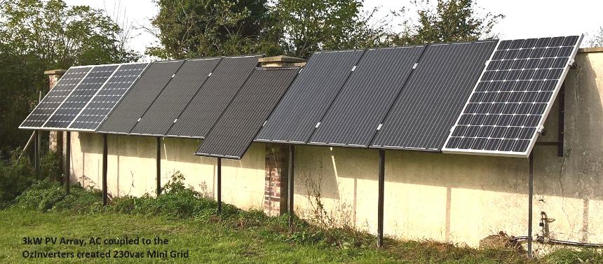
- PV. PhotoVoltaic panels, ………
Manufacturing costs for these PV panels has drastically reduced over the last 20 years, and therefore making Renewable Energy electricity production at a very good cost effective solution. All PV production is a DC voltage and this will need to be converted to a AC domestic voltage for a normal house.
On average 15,000 Watts, or 15kW is about for a normal dwelling/house, so 15kW of PV would take a required space/size in your garden with a PV array of between 20 meters by 5 meters and 25 meters by 3.4 meters
That would be for 60 panels at 250w each and 1.6m x 1m each, 3 rows of 20 would be 20 meters by 5 meters.
For the latest up to date more efficient PV panels at 330w that are 1.8m by 1.1m each, 3 rows of 16 would be a space of 18 meters by 5.4 metres.
In 2019 15kW of PV Mono Crystalline panels can be from 4.500e to 9,200 Euros.
In 2020 3.7kW of PV Mono Crystallinepanels, 10off 370w Longi PV panels with transport fees etc, $1920 or 1600 euros,
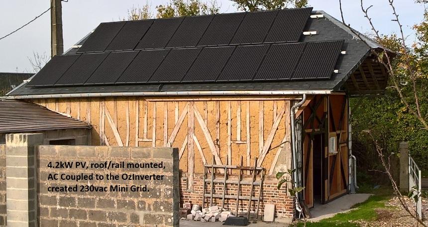
PV and slate tiled roofs.
France have taken the replace the slates/tiles with PV panels roof, and so did some other EU countries. Mostly done to stop Fraud as the Government were giving good resale grants on green electricity created and sold back to EDF, this has now been seriously reduced. However, after some roof fires in Holland, where the PV had started fires in the roof flammable insulation, Only France insisted on that method of install if you receiving or applying for FIT grant to sell back to EDF, Here at 'Le Vivray' we do not sell back to EDF so 'In the roof' system is not applicable. However, in France the last few years that policy is now relaxed, and i understand from the Fire Brigade, chat with our local Chief, Rail mounting is now being used.
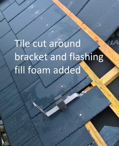
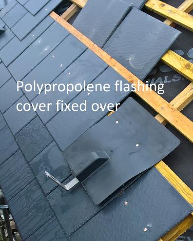
On a practical note, Most PV panels are only designed for a life of 20 years, so replacement at some time will be required. However, as you realize PV is getting more and more efficient and better output, and also changing physical sizes, so it’s a nightmare trying to fit different PV panels into a roof in the future. Me, NO way would i fit a in the roof installation. Those PV panels get hot i mean hot. Rail mounting means that the water integratory of the roof is not and never will be breached, that’s if the rail mounting struts are installed correctly with the correct flashings.
We have about 61 large PV panels, Monocrystalline type, large means output over 250w, with differing makes with our R&D, from the Rolls Royce, ie Sharpe/Panasonic makes, down to the cheaper brands like KNIVE. Only one has failed a KNIVE on a static wall mounted array, and that is due to an internal connection within the panels itself, and the heat generated has shattered the glass, but it is still in use and working, but it will get replaced sometime.
We also have some Old Amorphous silicon type PV panels, that I got in 1988 and installed here in 2008, these are used as garden water pumping arrangement. At some time, I will remove this poorly preforming array only gives 200w with 6 panels, and replace with a new array of 2000w for the same surface area. Yes, its amazing how technology has leaped forward these last 32 years.
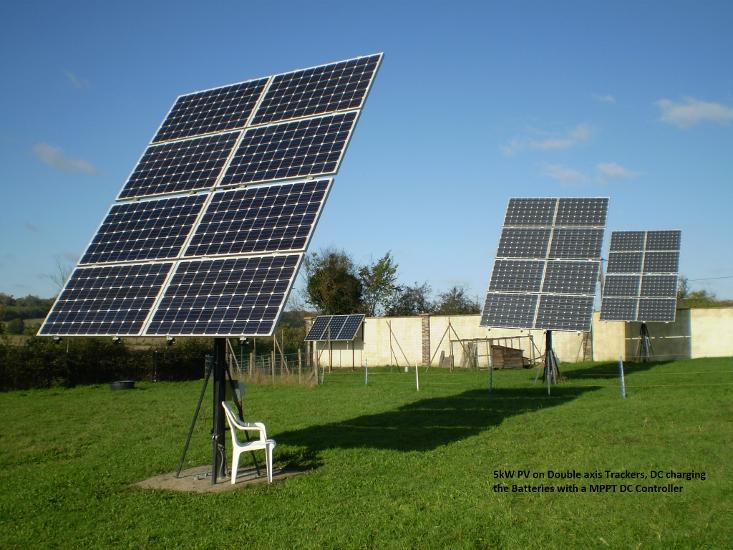
For best results, in the Northern Hemisphere, your PV should be directly facing the sun and angled to face the sun at Midday on the days of the Spring or Autumn Equinox
.
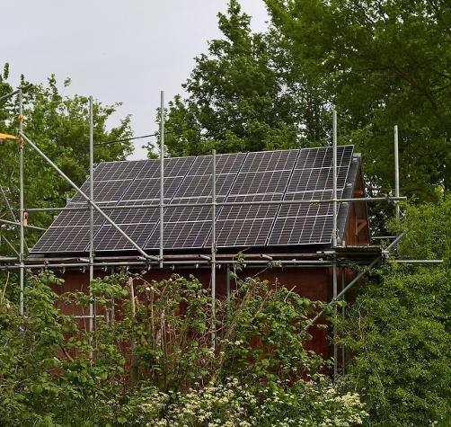
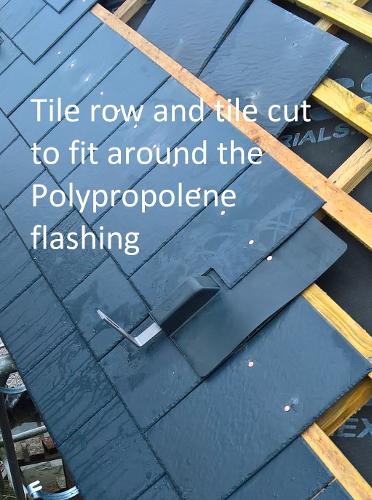
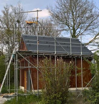
The Different stages of fitting a 3.6kW PV Photovoltaic Installation to a Slate Roof.
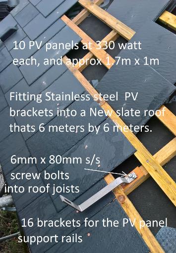
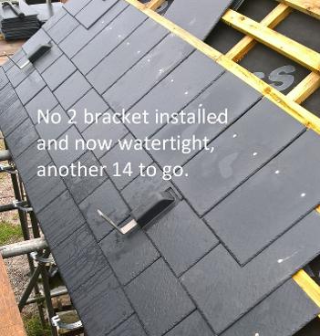
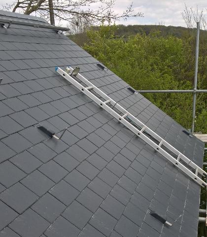
As this is a New Slate roof, 6 meters by 6 meters, its an ideal time to fit the stainless-steel support brackets on the south side of the roof, and these will hold the aluminium mounting rails.
Obviously, you should know the sizes of the PV panels you will be fitting as this will determine where and how the brackets and rails are mounted on the roof trusses. I lay out the roof slate lath’s first for the correct Lap of the slates, then its easy to clamber up and down on the roof laths.
On this roof I have put 4 support brackets for each of the 4off 5.8m long aluminium rails. Make sure these rail support brackets all line up so the rail is kept straight, and try and keep it square to the actual roof. 4 brackets per rail is minimum for 5.8m length, but it’s the roof trusses that the brackets mount onto that will determine the spacing. When working out the length of a rail, remember to allow for the panel clamp brackets' and allow an extra 200mm at each end as you will need the space to slide over the final PV panel to get your hand between the panels to do the underside connections. Remember the underside of the panel is a thin plastic membrane and very easily damaged.
NEVER, never walk on a slate roof as it will damage the slates and rain water will get into the building, so always use roof ‘crawler’ ladders that spread your weight. Once the aluminium rails are bolted onto the mounting brackets, then a normal ladder can be used that is laid on the rails, but please remember to foot the ladder so it does not slide off the scaffolding.
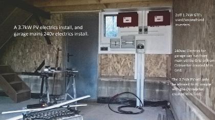
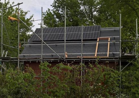
A 3.6kW Photovoltaic PV, electrics installation.
A 3.6kW Photovoltaic PV, and its electrics installation, that will join my other 14kW of PV that we have here that is also collecting the sun light.
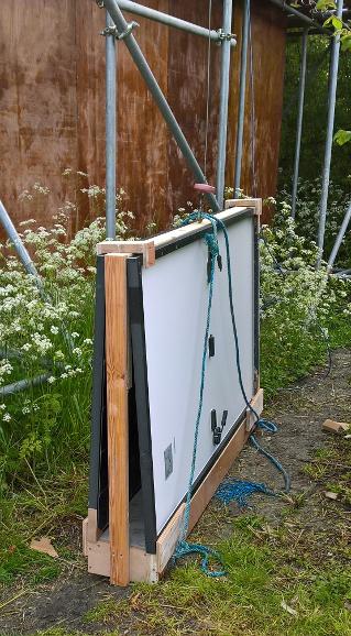
These are UpToDate, Dec 2020, LONGI 370w split monocrystalline PV panels, each panel is 1760mm x 1040mm and 35mm thick. Each has a maximum output of 40.5vdc at 9.1amps.
Firstly, SAFETY, High voltages are dangerous, if you are not sure then please!, please! ask a competent qualified person.
This electrics installation is for France and complies to the French regulations, which after all these years I actually like. The earth system here is a 1.5m rod bashed into the ground and linked to the distribution fuse boxes with a earth 16mm/2 cable. MCB’s here are 2 pole, so both N & L are protected, in France we do not use a common Neutral bond/bus bar, nor do we bond the Neutral to the Earth.
For this installation on the south side of the new garage slate roof, I have 2off used/second-hand 1700W SMA Grid Tied Inverters, GTI’s. These will feed into the OzInverter created 240vac Mini Grid. Therefore, I have split the 10off PV panels into 2 strings of 5 panels each, and those 5 panels will give a maximum of 202.5vdc at 9.1amps into each GTI.
The 2 GTI inverters will convert the 202.5vdc into 240vac and this will feed back into the OzInverter MINI GRID that is connected to all the 8 buildings here.
If the electricity being created by the PV is not being used around the buildings, then any excess will back feed through the OzInverter and re-charge the batteries. If the batteries are fully charged then the AC voltage will rise slightly by a few volts and shut the SMA GTI inverters down.
Please note, it is very important for the life and longevity of your batteries, that they MUST NOT BE OVERCHARGED.
So setting the GTI shut down voltage is specialised for each GTI, as its location for voltage drop/droop, and its own internal settings do vary. Dc battery voltage Comparator circuits can also be used to operate a relay at the GTI to shut it down. Another method is redirection circuit or specialised battery controllers that sends excess power to Dump Loads or other uses like underfloor heating or swimming pool heater etc.
Costs so far, the 10off Longi PV panels with transport fees etc, $1920 or 1600 euros, 2off SMA 1700 used GTI’s, total $204 or 170 euros.
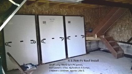
10 Longi PV panels, 1760mm x 1040mm propped up inside awaiting electrical testing. Longi say that these are 370w max output, but i will call them 360w. These are 120 cell monocrystalline type. Please note on these 120 cell panels the positive and negative power output feeds are centrally mounted on the back.
The Initial stage of installation of the electrical boxes and hardware, wire trunking and the 2 GTI Inverters installed.
NOTE ..... The white back board is plasterboard over a 18mm plywood backboard, its good as this install is inside a wooden garage, and it also gives the securing screws something to really grip into. And those GTI inverters are 30kgs each.
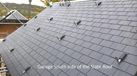
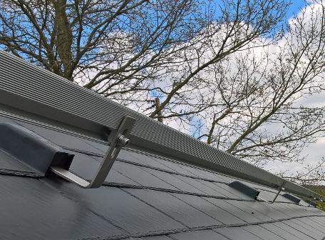
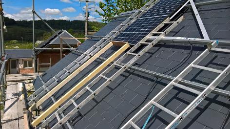
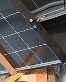
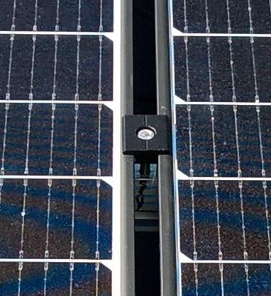
PV goes on the slate roof mountings.
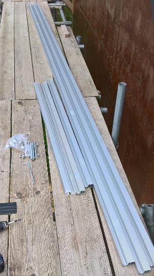
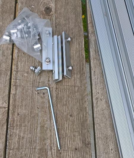
The system I have recently installed for mounting the PV panels is called GRASOL, and yes its no longer sold by Wholesalers and the like as they change suppliers fairly frequently. But all other systems, Fisher etc are very similar but not always interchangeable.
Each panel is 1040mm wide and each double holding clip between panels is 26mm and with the panel single end clips taking up 30mm and i allow a extra 200mm at each rail end. Most PV clip manufactures are now about the same. So i have made each of the 4 aluminium rails 5800mm long. These particular design of rails come at 4200mm long so I have added an extra 1600m. There are especially made aluminium joints with stainless steel Allen cap 8mm diameter threaded bolts. The underside of the rail is serrated along its length so gives a sure locking to the slate brackets and to the PV rails.
The other small locking 8mm threaded units in that plastic bag in the Photo is for locking the rail to the roof/slate upright bracket. Its adjustable so the rails can be kept level and straight with each other.
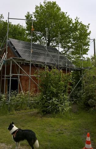
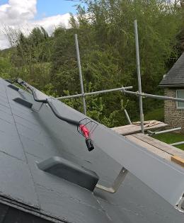
I always put good sturdyscaffolding up when doing a roof. And with PV on rails its a real pain getting a standard crawler ladder to go under the rails and be able to keep pulling the crawler out. So i use short ladders that i hang on a roof /slate/rail holding bracket, with the ladder footed at its base with a large wood block screwed, (6mmx 100mm), to the scaffold wood boards, that are in turn well affixed to the scaffolding. These 2 photos show the method.
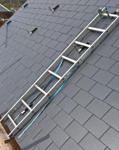
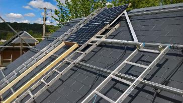
All 4 rails now firmly attached and awaiting a non windy day to fit the PV Panels, I have no help here as the Covid brings many regulations on travel and Curfews here in France, so I have to do all the handling on my own, and as you will see I have made some wood JIGS/Frames to assist me safely, and installed the electric winch. Its good for 200kg so i can lift 2 PV panels at a time with a special lifting cradle as each panel weighs about 16kg.
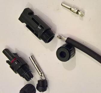
Once the rails are affixed the cabling feed wires can be installed from the DC Isolator control boxes on the internal main electricity Inverter board. As this is 2 strings of 5 Panels, each string is wired up in series connection so the top string will require a positive cable on the left side of the roof and a negative cable for the right side. But check first how the panels themselves are wired. The electric cable used for PV installations is a special solar cable and it has thick insulation as its UV stable and has a internal stranded wire of normally 4mm/2, however I prefer to use 6mm/2 on long cable runs. The connectors used with PV are called MC4 connectors and come as male and female and once connected are supposedly waterproof.
Most PV panels come with the MC4 cables and connectors already installed and they will readily interlink between each panel, but keep the cables tidy and use plenty of cable ties to hold them in place. The 4off long main feed 4mm/2 or 6mm/2 solar cable will require appropriate MC4 connectors being attached to the solar cable, I solder, but most are crimp.
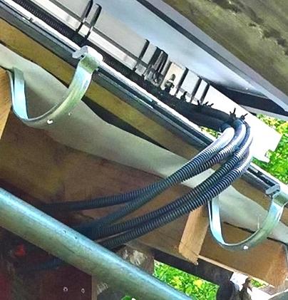
These solar cables will also require some sort of trunking to support them and to protect them from the severe elements of the weather. I use a black supposedly UV stable non inflammable flexible trunking about 18mm in diameter.
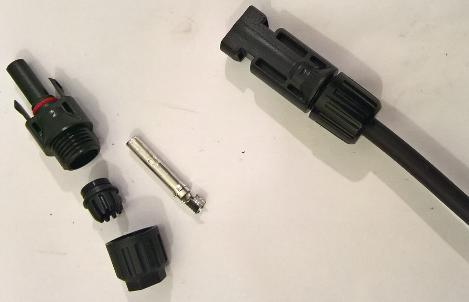
The 2 photographs below show a male and female MC4 connector being assembled, and the finished Female MC4 connector and cable.
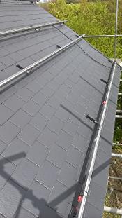
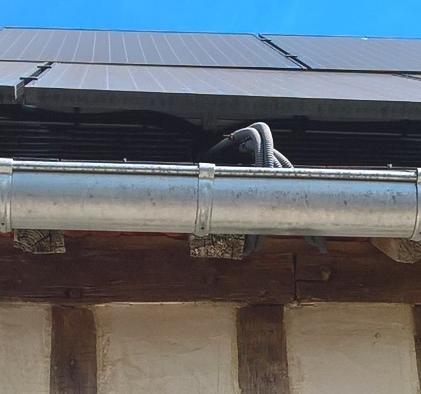
Where the Solar cables enter the Building, I allow extra slack so that it can go around and tuck under the roof tiles and up and over the guttering and allow a little sag, allowing water from the guttering if it ever overflowed, to drop off the cables before the cables enter the building. One photograph shows an installation where the cables go around the guttering, and the other photograph is before the guttering is fitted. Note, you can see that I put red tape around the Positive cables. Please remember that once the last PV MC4 connector is joined, these cables will have over 200vdc going through them, so be very careful.
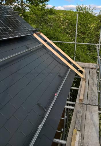
As I have already mentioned on this particular installation, May 2021, I was completely on my own. So, I have had to take safety measures and manufacture some wood frames and gauge sticks to hold the PV panels in position while I clamped them down to the PV rails.
I always start with the central panels on the top row of a roof, and here I have had to make a wood frame to keep the PV panel in its exact position on the 2 top rails. Don’t forget to ensure that the bottom row of PV panels will drain into the gutter.
In these photographs you can see the first central PV panel going on. I lower the panel onto the bottom rails and carefully slide it up to the top 2 rails and therefore onto the wood frame. As you can see all ladders are now resting on the PV rails.
On the above photograph you can see that I have used a folding 90-degree Square, to ensure that the PV panel is square to the rails. If you do not get the first PV panel square then the panels will get worse towards the end of the roof and also put the bottom row out as well.
Note, about the PV Panel holding clamps……… The between PV panel holding clamp will hold when both are tightened up, but only temporary, if you need to hold overnight then use the end of rail single PV clamps. The first PV panel will require end of Rail single holding clamps, until another PV panel is alongside for the double PV clamp. Also the nut should fit into the aluminium rail, but sometimes they stick as the tolerance is very tight, I just use a piece of wood to tap the 8mm diameter holding clamp Allen bolt.
These 2 photos show the PV panel support frame awaiting the next PV panel and at the same time supporting the left-hand panel before the double clamps are fitted.
You can see in these photos that I am using screwed down wood blocks to foot the wood frames and the ladders so nothing slides of the scaffolding.
The photograph to the right shows the bottom row of PV panels being fitted. And here again I just use several blocks of wood screwed down to the scaffolding to hold each panel in the correct position.
The wood stick is a gauge stick and is exact the height/length of the PV panel, 1760mm plus about 8mm, so once fitted the PV panel will have about 10mm clearance from the top row of Panels.
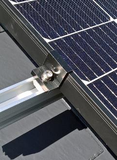
Photo above shows a single end PV clamp. Note, each actual height of PV panels frames are different depending on the manufacturer, so ensure your mounting clips/clamps are the correct size.
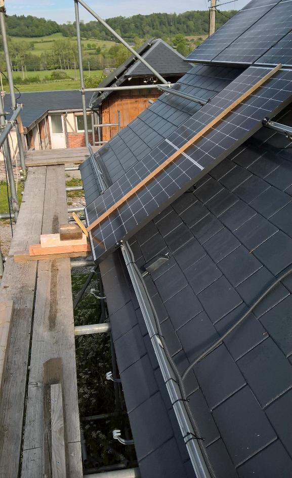
Photo below is a double PV clamp awaiting another panel before clamping both.
And right photo, a double clamp doing its job.
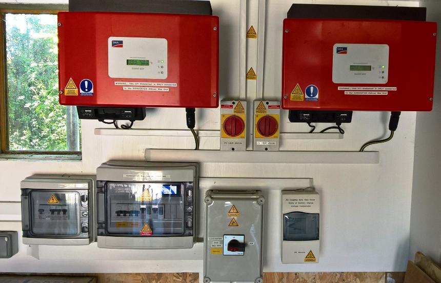
The Used/second hand SMA 1.7kW Grid tie Inverters doing there job, and AC Coupled and feeding back into the OzInverter created 236vac Mini Grid.
Please Note, ..... These 2 GTI's Inverters will only operate from and into the OzInverter MINI GRID. That large changeover lockout switch ensures this.